[Merge DWG] Function
Function Description
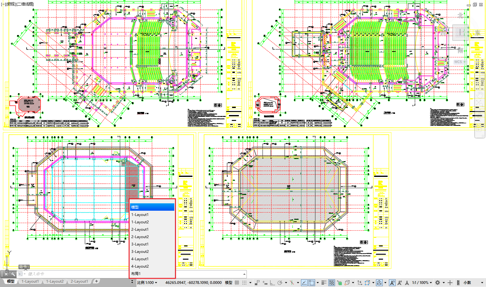
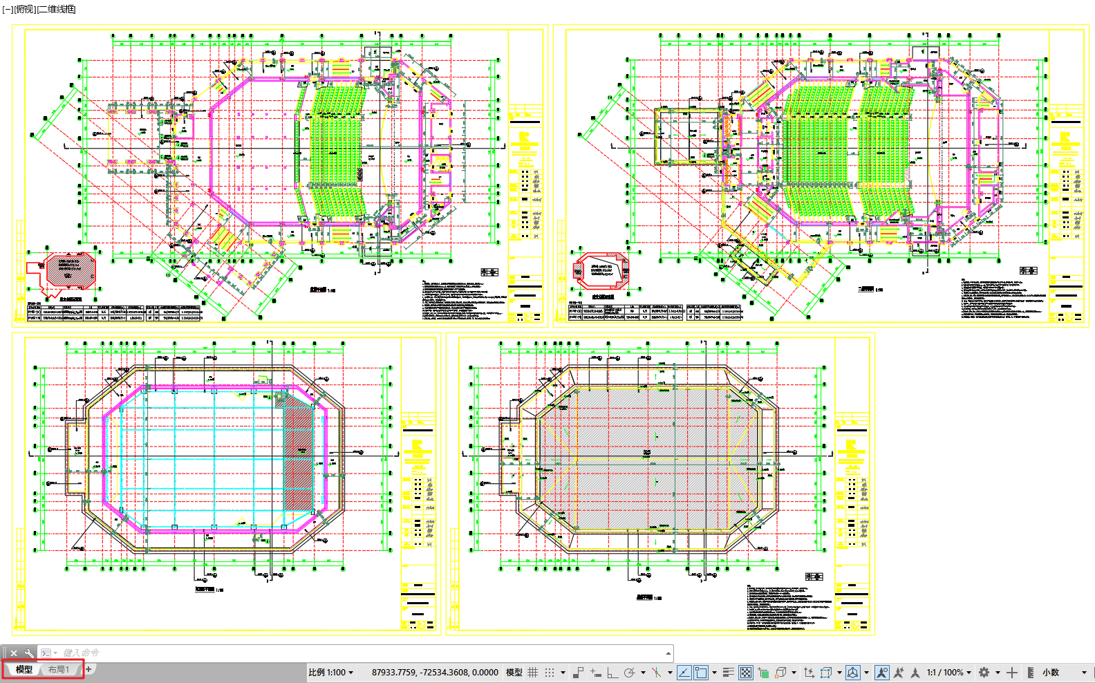
This feature allows multiple exported DWG drawings to be combined into a single DWG file by arranging them in rows and columns. It solves the problem of having to open multiple drawings to view a project—after merging, users can view all project drawings in one DWG file without switching between multiple files.
Notes
DWG files from different directories can be imported into the target file list for merging.
Operation Steps
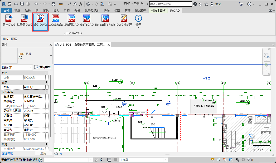
1. Execute the [Batch Export DWG] Command
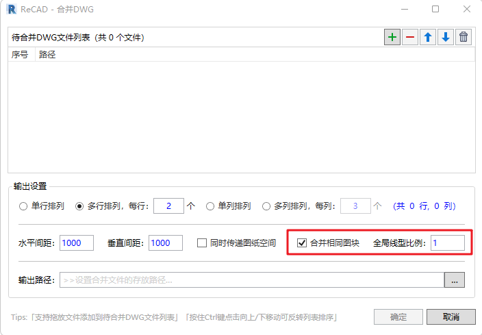
In the “ReCAD” ribbon tab, run the [Merge DWG] command from the “uBIM ReCAD” toolbar. After execution, the “Merge DWG” window will appear.

2. Set the “DWG Files to Be Merged” List
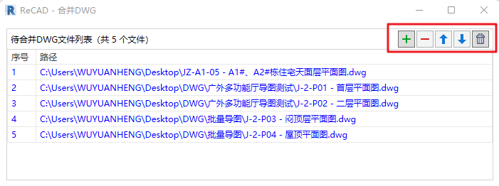
 You can import DWG files from different folders into the “DWG Files to Be Merged” list.
 You can remove specific DWG files from the list.
 You can clear all files from the imported list.

 You can define the arrangement order of DWG files.
📝Notes
1.This feature supports adding DWG files to the list of files to be merged by dragging and dropping them.
2.Hold down the Ctrl key and click Up/Down to invert the order of the original file list.
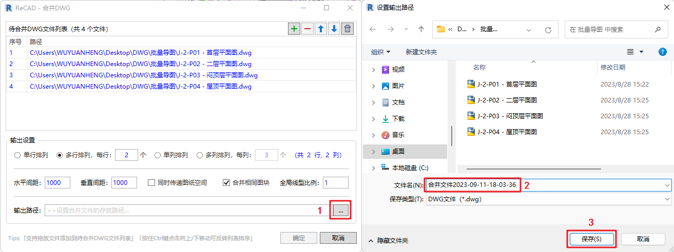
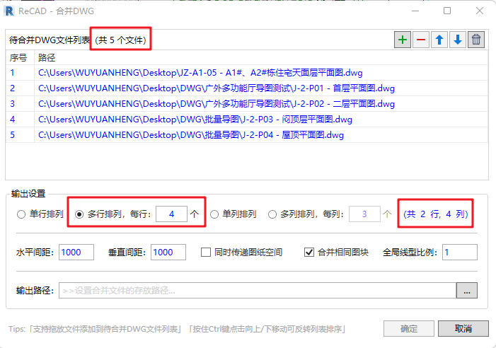
3. Define “Output Settings”
In the Output Settings section, users can arrange the imported DWG files in rows and columns as needed.
- When Row is selected as the primary option, the Column setting will be automatically locked. Likewise, when Column is selected as the primary option, the Row setting will be locked. For example, when using the Row setting, users can define single-row or multi-row layouts and specify how many drawings to place in each row. The value shown in parentheses will automatically calculate the total number of rows and columns based on the total number of DWG files.
- The default spacing between drawings is 1000 mm both horizontally and vertically. Users can adjust these distances according to their actual needs.
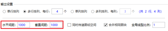
- Users can check “Include Paper Space” to ensure each drawing exports its own paper space.
- When exporting the merged DWG file, it is recommended to check “Merge Identical Blocks.” The global linetype scale is set to 1 by default, but users can modify this value based on their specific requirements.
4. Set the Output Path for the Merged File
Users need to specify the export path for the merged DWG file. The setup method is shown in the figure: