[Export DWG] Feature
Feature Description
This feature allows the plugin to automatically detect areas in DWG drawings exported from Revit that do not comply with drafting standards and quickly correct them according to professional specifications. This significantly reduces the workload of BIM drafting and greatly improves efficiency.
Notes
1.Open the view you want to export before executing the command.
2.Only available in floor plans, sections, elevations, and detail views.
3.Supports exporting floor plans, sections, elevations, detail views, drafting views, area plans, legends, and sheet views.
Steps
1. Select Sheet View
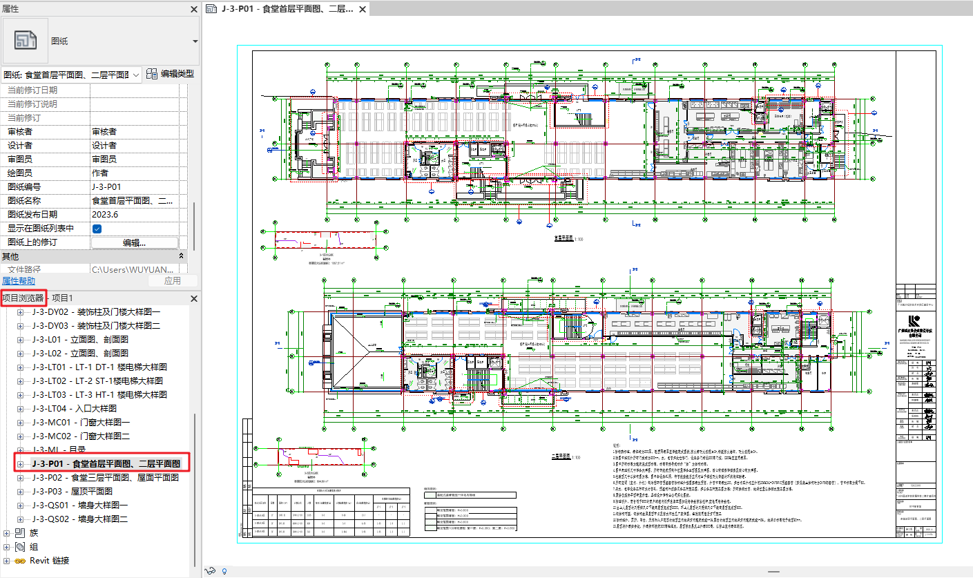
In the Project Browser, double-click to open the sheet view to be exported.
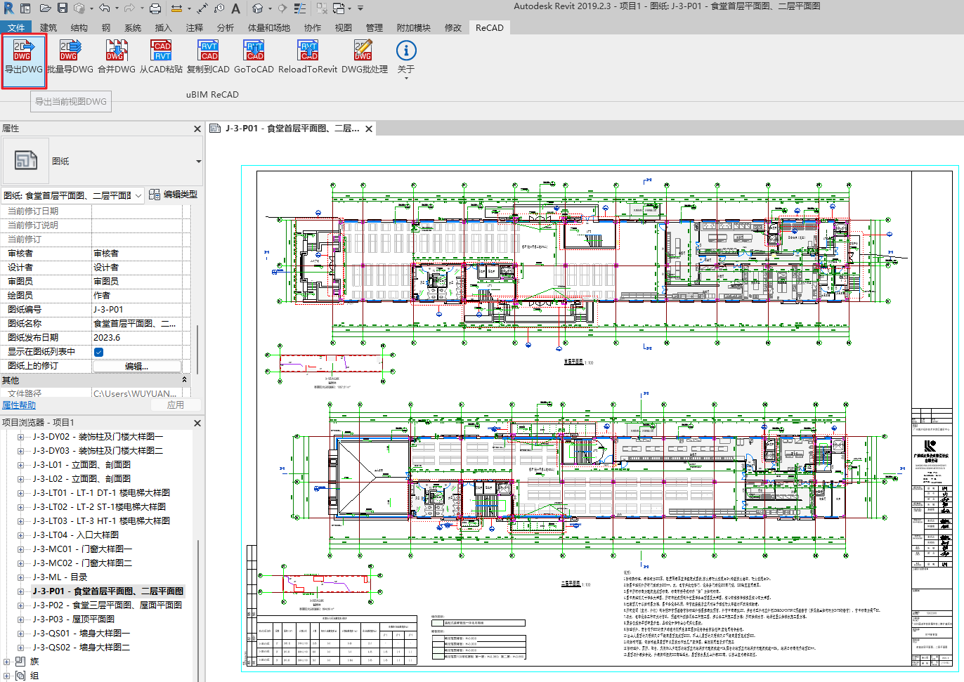
2. Execute [Export DWG] Command
In the ReCAD tab, execute [Export DWG] from the uBIM ReCAD toolbar. This will open the DWG Export Settings window.
3. Set Export Parameters
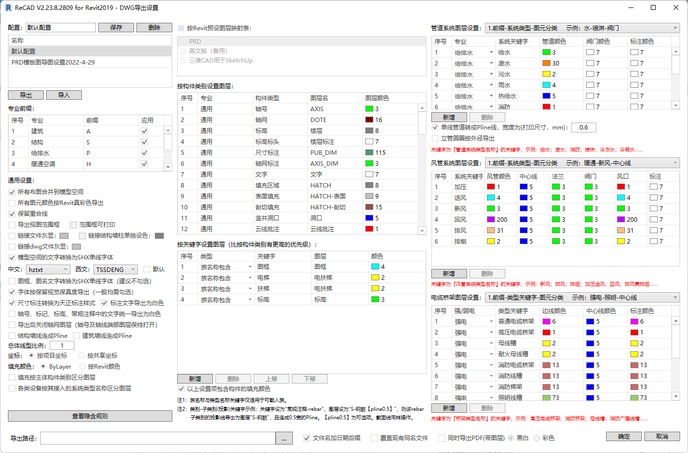
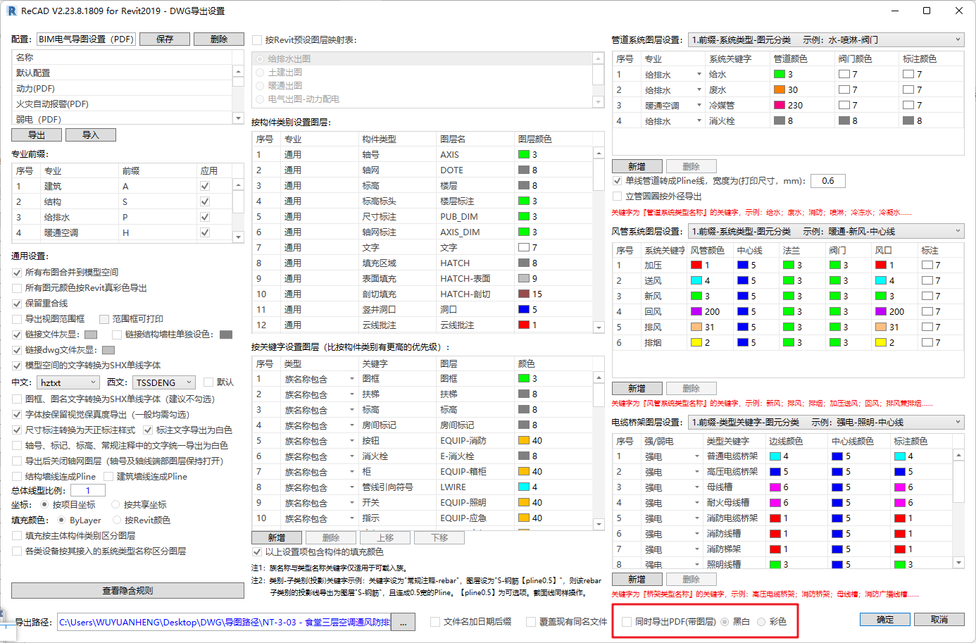
In the DWG Export Settings window, you can configure export parameters including professional prefixes, general settings, layer settings by category, layer settings by keyword, pipe system layers, duct system layers, cable tray layers, etc.
Users can also import/export configuration parameters and save or delete them. Detailed settings include:
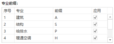
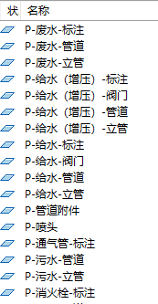
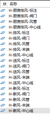
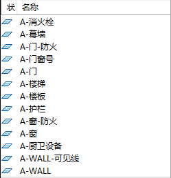
- Professional Prefix: Standardizes layer names by discipline. The adjusted layers are shown in the images below.

General Settings: Select options to ensure DWG layout, fonts, line types, and other drawing effects comply with professional drafting standards and habits.
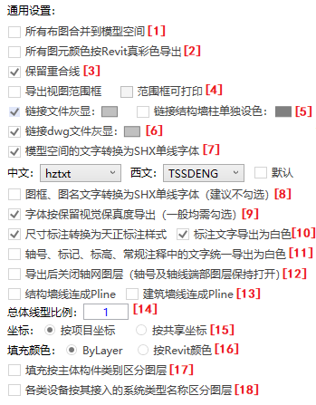
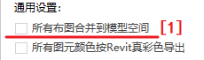
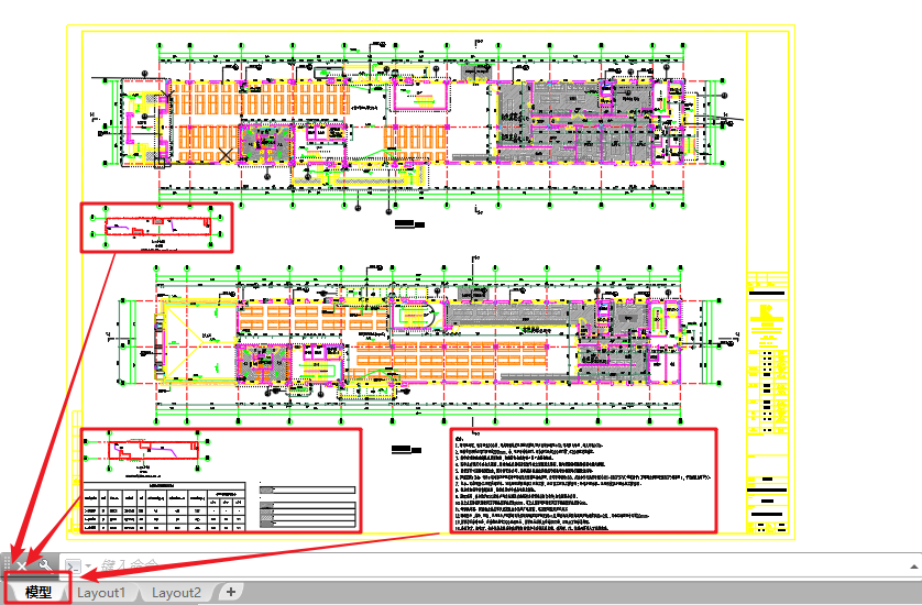
1.Merge all layouts into model space. This option is selected by default to fix the limitation of Revit’s native export, which cannot merge layouts into model space according to predefined arrangements.
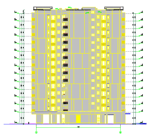
2.Export all elements in true Revit colors. Select this if you want the exported DWG to preserve the element colors defined in Revit.
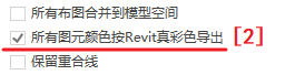
3.Keep overlapping lines.
4.Export view range box, which is printable.
5.Display linked files in gray, while linked structural walls and columns can have distinct colors.
6.Display linked DWG files in gray.
7.Convert model space text to SHX single-line fonts. Revit’s native DWG export uses TrueType fonts by default, which do not meet drafting standards. ReCAD converts model space text to SHX single-line fonts for proper drafting.

8.Convert title block and sheet name text to SHX single-line fonts (not recommended by default). Export does not select this by default; the font style for title blocks differs from annotation text. Select this only if you want unified fonts.
9.Export fonts while preserving visual fidelity (generally recommended).
10.Convert dimensions to TArch annotations, with dimension text exported in white.
11.Export axis numbers, markers, levels, and general annotations in white.
12.Close grid layers after export (axis and axis-end layers remain open). Users may select this based on professional drafting standards.
13.Merge structural wall lines and architectural wall lines into polylines (Pline).
14.Overall line type scale.
15.Coordinates: export using project coordinates or Revit coordinates.
16.Fill colors: by layer or by Revit color.
17.Assign fills to layers according to main element categories.
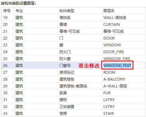
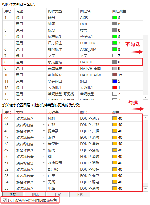
18.Assign equipment to layers based on the system type they belong to.Set Layers by Category: Includes architectural (walls, doors, windows, furniture), structural (beams, columns, slabs, structural walls), and common (grids, dimensions, fills) layers.
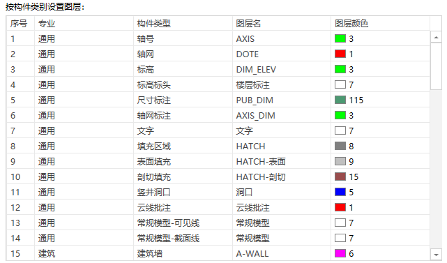
To modify a layer name, directly enter the new name in the Layer Name column of the corresponding discipline.
To change a layer color, click the color cell and select the desired color in the CAD Color Picker window, as shown in Figure 30.

- Set Layers by Keyword: You can modify layer names and colors based on keywords contained in family names. This rule has a higher priority than the Set Layers by Category rule. If an element matches both rules, the layer will be determined according to the keyword rule.
- The rules for modifying layer names and colors are the same as those in Set Layers by Category (see Figures 29 and 30 for reference).
- You can add new keyword-based rules according to project needs and adjust their order or priority.
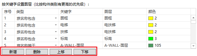
- Selecting “Include fill color of elements” ensures that both the element color and its fill color follow the layer color defined in the Set Layers by Keyword window. If not selected, fill colors will follow the Set Layers by Category settings.
📝 Notes
1.Keywords of the types “Family Name” and “Type Name” apply only to loadable families.
2.In “Category–Subcategory (Projection/Section)”, the keyword-based layer settings include lineweight definitions. For example, if the layer setting is “DisciplinePrefix–Component[pline0.5]”, the projection/section lines for that category will be exported to the layer “DisciplinePrefix–Component” and joined as polylines with a width of 0.5.
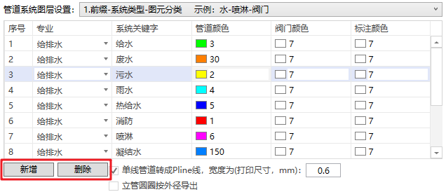
- Piping System Layer Settings: Includes configuration for piping system prefixes, system keywords, pipe colors, valve colors, and annotation colors.
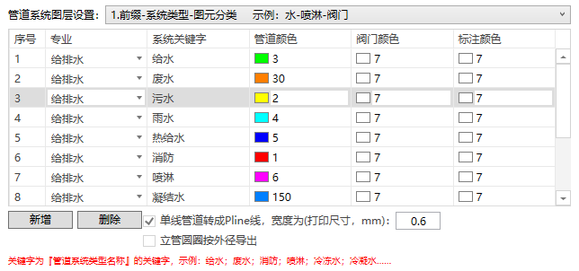
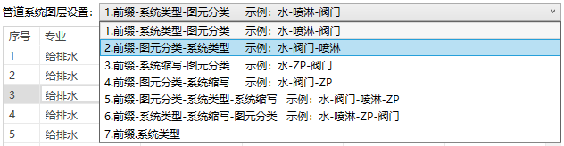
- The piping system layer prefix offers multiple styles; users can select the desired one from the dropdown list.
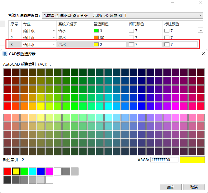
- To modify a keyword, directly enter the new name in the System Keyword column of the corresponding discipline. To change the pipe color, valve color, or annotation color, click the respective color cell and select the desired color in the CAD Color Picker window.
- You can add new piping system layer rules according to your project’s requirements.
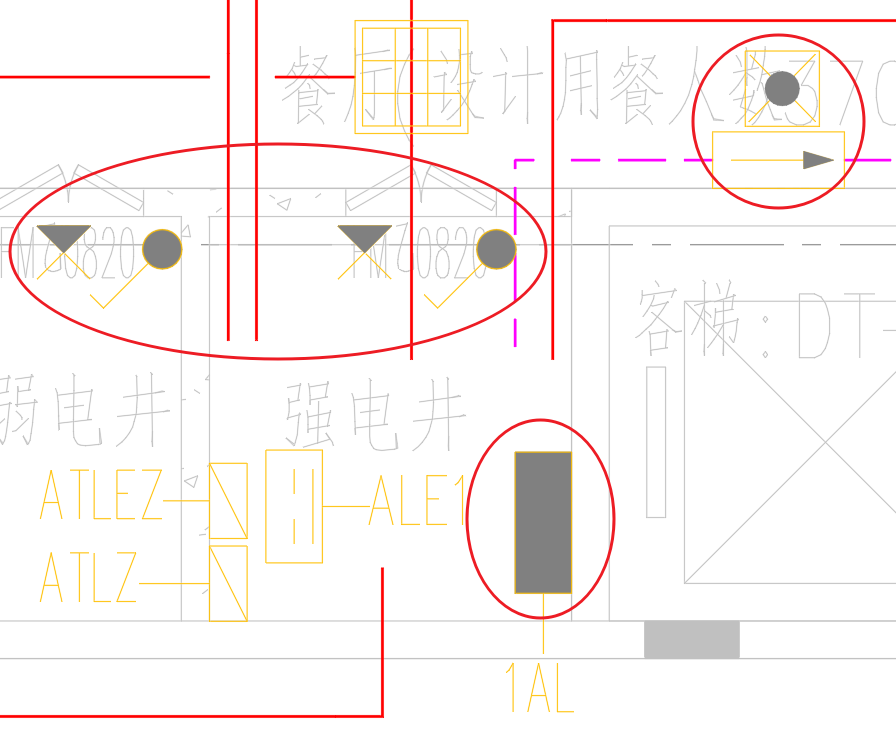
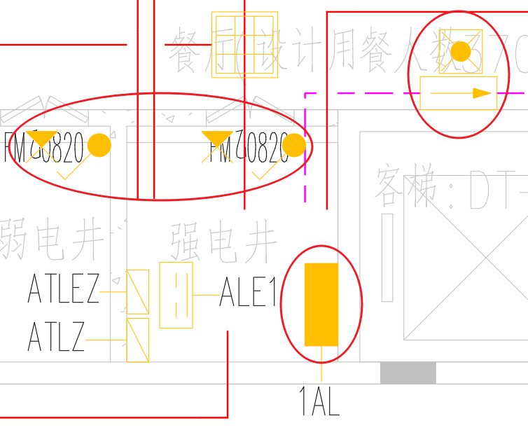
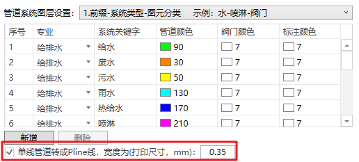
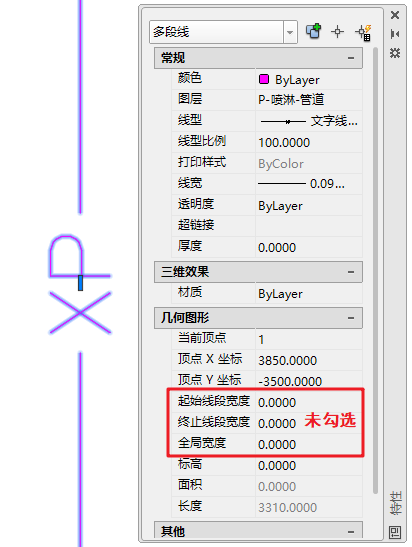
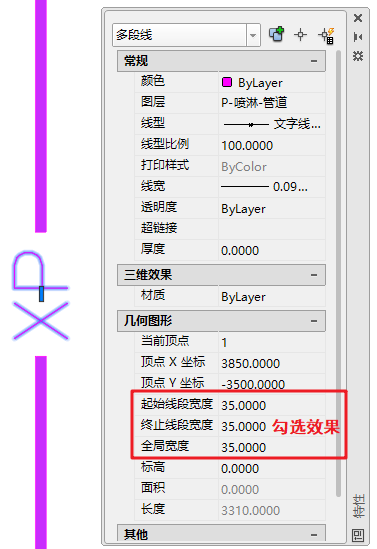
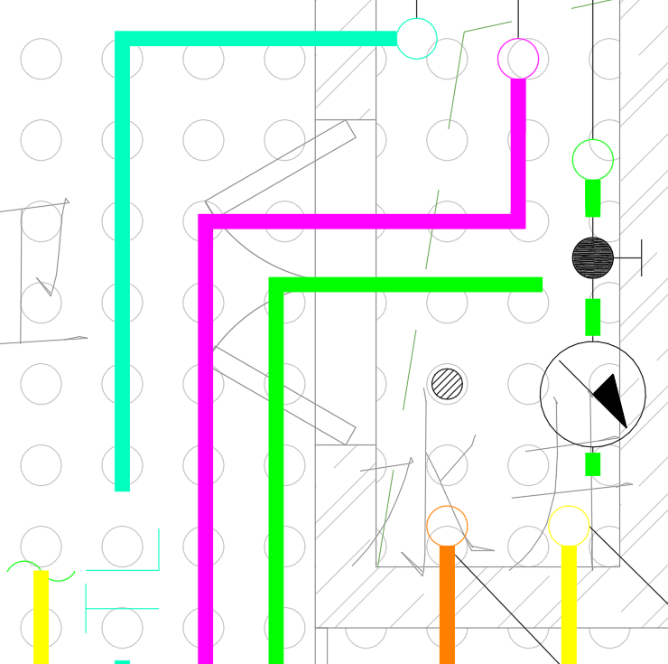
- Check “Convert single-line pipes to polylines” to export plumbing and piping lines as polylines with a specified width instead of single lines. For example, when this option is selected, plumbing lines will be printed as Pline with a width of 0.35 mm, as shown in Figure 37.
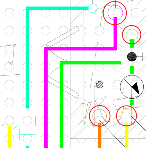
- By default, vertical pipe symbols for plumbing are exported as circles with a diameter of φ100. If needed, check “Export riser circle by outer diameter” to export riser circles using the actual outer diameter of the placed pipe.
📝 Notes
which represents a letter height of 1.8, spacing of 20, and a default linetype scale of 100. (This rule applies only when exporting pipes in single-line mode.)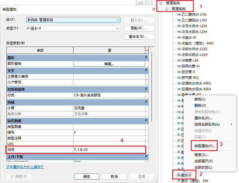


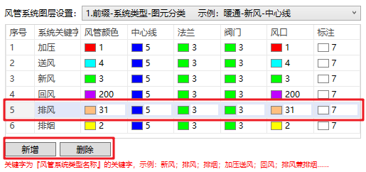
- Duct System Layer Settings:Includes configuration for duct system prefixes, system keywords, duct colors, valve colors, diffuser colors, and annotation colors.
- The duct system layer prefix also offers multiple styles; users can choose the appropriate one from the dropdown list, as shown in Figure 39.
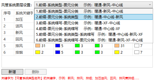
- To modify a keyword, directly enter the new name in the System Keyword column. To change the duct color, centerline color, valve color, diffuser color, or annotation color, click the corresponding color cell and choose a color in the CAD Color Picker window. Additionally, new duct system layer rules can be added based on project requirements, as shown in Figure 40.
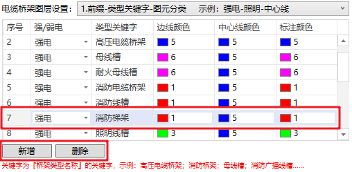
- Cable Tray Layer Settings: Includes configuration for cable tray prefixes, type keywords, edge color, centerline color, and annotation color.
- The cable tray layer prefix also provides multiple style options; users can select the appropriate one from the dropdown list, as shown in Figure 41.
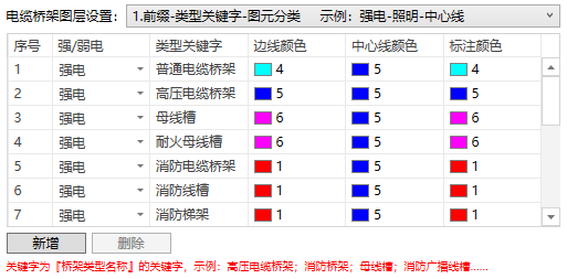
- To modify a type keyword, directly enter the new name in the Type Keyword column. To change the edge color, centerline color, or annotation color, click the corresponding color cell and choose the desired color in the CAD Color Picker window. New cable tray layer settings can also be added according to project requirements, as shown in Figure 24.
- For wires or conduits that need to be exported as alphabetic linetypes, the linetype styles can also be defined. Detailed instructions can be found under General Settings → Hidden Rule Description. The procedure is the same as the setup for exporting single-line piping systems as alphabetic linetypes, described above.
4. Export File Settings
After completing the DWG export parameter configuration, you need to specify the relevant settings for the exported files.
- Export Path Settings:The user must specify the export file path — without it, the drawings cannot be exported. The setup method is shown in Figure 43.
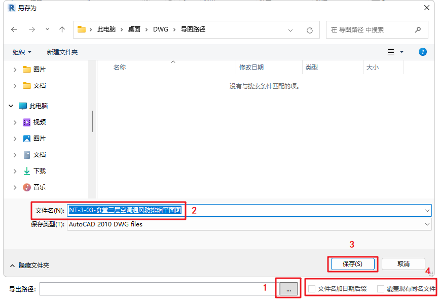
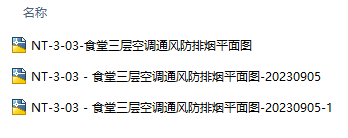
- By default, the exported drawing file name is identical to the name of the opened view/sheet.
- To append the export date as a suffix to the file name, enable “Add date suffix to file name”.
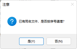
- When performing multiple exports: If you wish to keep all previous export files, make sure “Overwrite existing files” is unchecked. In this case, files with the same name will automatically receive incrementing numerical suffixes. If “Add date suffix” is not selected, the second export will automatically generate a version with a date suffix, and subsequent exports will follow the numerical increment rule.
- PDF File Export Settings
The ReCAD plugin allows exporting layered PDF files simultaneously when exporting DWG files — a feature that differs from Revit’s native export. The plugin can automatically detect the title block size to generate properly scaled PDFs. In addition, users can select whether to export in Black & White or Color appearance styles according to actual requirements.
5. Confirm Export
Finally, after verifying all settings are correct, click Confirm to start exporting the drawings, as shown in Figure 46.

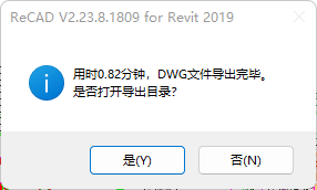
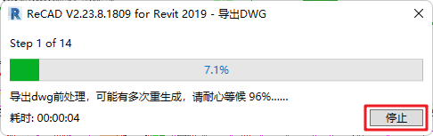
- During the process, a progress bar and elapsed time counter will appear. Once the export is completed, a notification dialog will display the total export time and provide an option to open the export directory.
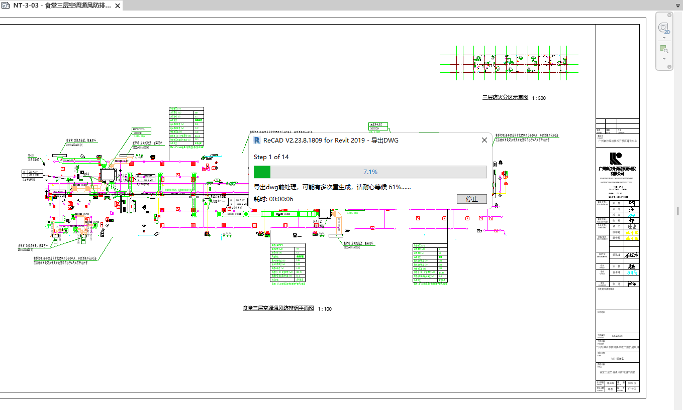
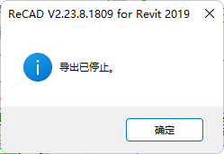
- If you wish to cancel the export during the process, click Stop in the lower-right corner of the progress dialog. The export will be terminated, and a message box stating “Export stopped” will appear, as shown in Figure 48.
The above five steps constitute the complete ReCAD drawing export workflow.
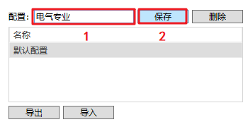
Additionally, since different project types and standards may require different export configurations, users can save and reuse custom export settings to avoid repetitive setup.
- Create a New Configuration: Enter a configuration name in the input field and click Save to create a new configuration, as shown in Figure 49.
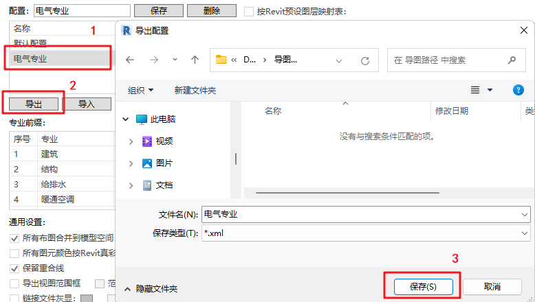
- Export Configuration: Click Export, specify the save path, and then click Save.
When the “Save successful” message appears, the configuration export is complete, as shown in Figure 50.

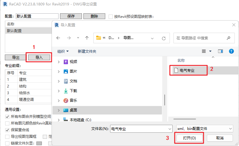
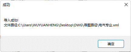
- Import Configuration: Click Import, select the desired configuration file (*.xml), and when the “Import successful” message appears, the import is complete, as shown in Figure 51.